Overview
Part Construction
The first parts that were produced were the top and lower beams of the side trusses. These parts were simple in their design only needing one cut per part and minimal sanding to bring them within the specifications of the design. The parts were cut in a small miter box using a fine toothed hobby saw, then sanded to smooth out any saw marks.
The cross beams were manufactured using the same methods as the previous parts, just on a smaller scale.

The bulk of the manufacturing process was spent making the tension and compression support members. The parts had more complex geometry due to the angles on the ends of the parts. There was a 20% failure rate on the go-no-go check for these parts.
The image to the right shows the two part types that make up the majority of the truss. The right part is the support member, and the left part is the truss cross beam.

The pieces were then glued together and pressed against the miter box to keep the joints consistent. Afterwards a protractor was used to measure the angle of the pieces to verify it would set at 60 degrees from the horizontal.

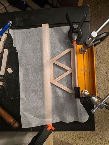
The truss elements from the previous video were then glued together with an additional truss cross beam. This step represents one third of the side truss assembly. The part was set using the help of strips of bass wood to set the additional member in place.

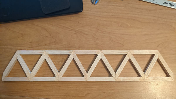
The second to last step of the side truss was combining the all of the previous sub assemblies to to the truss on the right. The excess glue was then cut of to reduce weight, and the imperfections on the joints were sanded off. All that remained was laminating the upper and lower beams onto the truss.
.jpg)

The articulation system was constructed over a two day period due to last minute changes to the design. All of the 3D printed parts were pulled from the previous design but the steel frame was an entirely new design. The wood pieces on the left side of the frame were placed to allow a pivot point for the hinge so the articulation height could exceed the 140 mm minimum.


The circuit used to lift the bridge utilized an Arduino sparkfun board to power two push button and two servo motors. The wires were set so that when the green button was pressed the servo motors would rotate at similar rates to lift the bridge. When the red button was pressed the servos would lower the bridge.